Jim Mimlitz, NRI
At custody transfer stations — and pumping stations in general — it is often necessary to supplement the level of disinfectant in the potable water. The purpose of this article is to discuss an effective and efficient technique that Navionics Research has developed that offers the following key features:
- Influent Flow Disinfectant Level Monitoring
- Disinfectant Pump Speed Control
- Disinfectant Pump Flow Monitoring/Verification
This article presents these techniques in the context of a successful recent project at a Rural Water District in Illinois. However, the methods discussed could be extended to other disinfection chemistry.
Influent Flow Disinfectant Level Monitoring

Because the Water District featured in this article is a rural system with distribution that spans hundreds of square miles, a supplemental boost of Miox is required, so as to maintain sufficient disinfectant levels between the custody-transfer pumping stations and all end-users.
In order to begin, the chlorine level (measured in parts-per-million, or ppm for short) of the incoming water is quantified. The operator has a higher chlorine level goal that is desired for the outgoing water, which he selects based on measurements, seasonal temperatures, EPA regulations, and experience. The target disinfectant level is selected to provide sufficient disinfectant throughout the far reaches of the distribution system.
In order to quantify a baseline measurement, water from the bulk supplier is drawn from the pressurized pipeline at the custody transfer pumping stations, through a pressure-reducing valve, and into a reagent-less chlorine monitor. The chlorine monitor continuously analyzes the water and transmits a 4-20mA signal to the Telemetry Control System for reporting and logical control purposes. An example influent chlorine level might be 2.1 ppm.
Disinfectant Pump Speed Control
The Telemetry Control System then performs automatic control calculations, so as to provide the optimal dosage of supplemental disinfectant from an on-site Miox Generator.
For example, if the outgoing pump flow is 600 gallons per minute (gpm), and the target disinfectant level is 3.2 ppm, and the disinfectant holding tank contains an aqueous solution of 2000 ppm Miox, then the desired disinfectant pumping rate can be calculated as follows:
Example Calculation:
Target Disinfectant Flow Rate =

= [Desired ppm - Incoming ppm] x [Booster Pump Flow (Gal/Hr)] / [Disinfectant Concentration ppm]

= [3.2 ppm - 2.1 ppm] x [600 gpm x 60 hours/min] / [2000 ppm]

= 19.8 gallons/hour
At this custody transfer station, the disinfectant pump featured a 4-20mA speed control input. However, the disinfectant rate-of-flow was not a linear function of the 4-20mA speed reference signal. In order to provide accurate disinfectant control, flow measurements were performed at various speed reference signals, and a cubic-polynomial curve-fit equation was developed to relate target disinfectant flow rate to speed reference signal. The correlation of the curve-fit to the measured data was excellent, as illustrated below.
| Speed Ref (%) | Chem Flow Metered (gph) |
| 0 | 0 |
| 10 | 0 |
| 20 | 0 |
| 22 | 0 |
| 28 | 4.77 |
| 34 | 9.64 |
| 40 | 15.32 |
| 44 | 19.19 |
| 46 | 21.62 |
| 50 | 25.23 |
| 58 | 37.84 |
| 80 | 64.86 |
| 100 | 74.4 |

Speed Reference (%) =

= 0.00031933*(GPH^3) - 0.033008*(GPH^2) + 1.73771*(GPH) + 20.880
Disinfectant Pump Flow Monitoring/Verification
In order to verify that the system was functioning properly, a 5/8″ positive displacement pump was installed by the operator in-line with the the Miox Pump; and the metering signal was interfaced to the Telemetry Control System via a SCADAmetrics EM-100 EtherMeter Flow Meter Gateway.

Miox Pump and Metering System. The Meter is a Badger 5/8″ Model 25 outfitted with an HR/E High-Resolution Encoder.
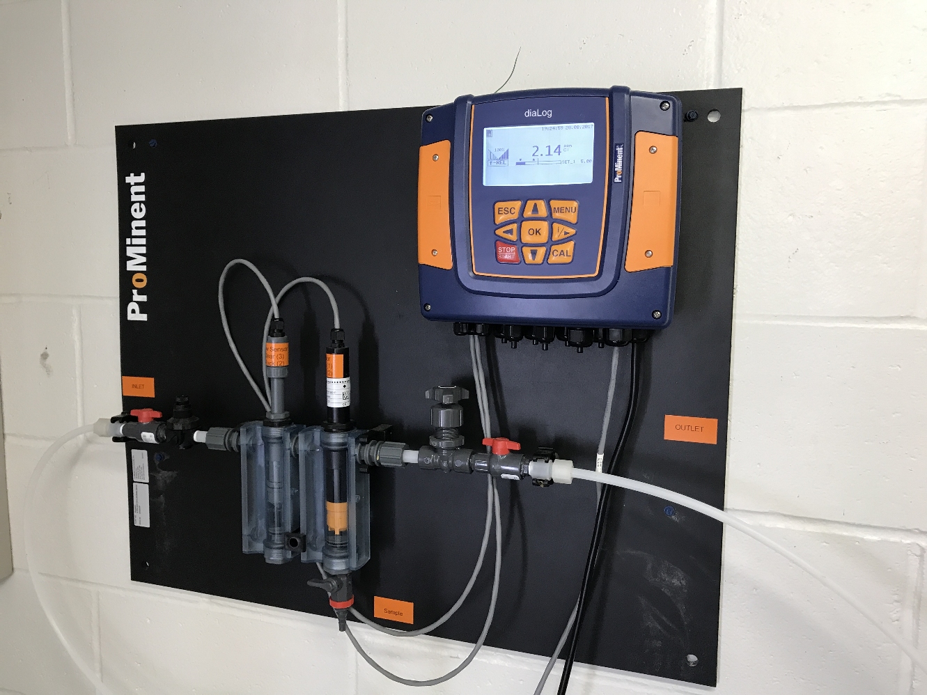
The Chlorine Level of the Bulk Supplier’s Water is Measured with a Reagent-Less Chlorine Monitor.

The Miox Disinfectant Pump Flow Rate and Total is Measured by a SCADAmetrics Model EM-100 EtherMeter. The Analog Signal from the Chlorine Monitor was Connected to the EtherMeter’s #1 Analog Input Channel. The 4-20mA Analog Output Speed Reference Signal for the Miox Pump was Generated by an Advantech ADAM-4024 Modbus Module. The Panel was Powered by an Isolated DC-DC Converter, and the RS-485 Modbus Signal Was Also Run Through An Isolated Repeater.

The Station’s Miox Generator and Holding Tank.
Performance
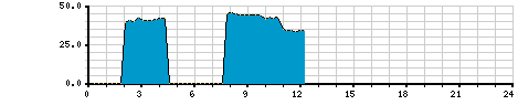
Partial 24-Hour Chart: Miox Pump Speed Reference Signal (0-50%), Provided by the Telemetry Control System. In this case, the Relationship Between Miox Flow GPH and Reference Signal is Non-Linear.
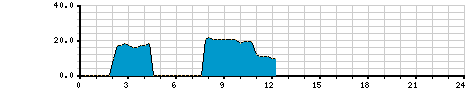
Partial 24-Hour Chart: Miox Rate-of-Flow (GPH), As Measured by an Inline Positive Displacement Flow Meter and a SCADAmetrics EtherMeter.

Partial 24-Hour Chart: Total Miox Consumption, As Measured by an Inline Positive Displacement Flow Meter and a SCADAmetrics EtherMeter. Units = CentiGallons (Gallons/100).
As illustrated by the above SCADA history charts, the Miox rate-of-flow is non-constant, as it is varied continuously so as to provide a constant and stable residual into the distribution system.
Are you interested in implementing much tighter control and vigilance over the disinfectant residuals at one or more of your critical pumping or water treatment stations? We offer experience providing this capability — and many more. Give us a call, and we’ll be glad to discuss this with you in further detail.
Telemetry, SCADA, & Controls Newsletter
Was this article helpful? Would you be interested in receiving updates such as these in our occasional email-delivered newsletter? If so, here’s our sign-up page:
Subscribe to Navionics Research’s “Telemetry, SCADA, & Controls Newsletter”