Jim Mimlitz, NRI
The High-Performance Butterfly Valve offered many advantages over the diaphragm valve, especially in the area of control system integration. For example, when the connected controls are closely monitoring the valve’s rate-of-flow and the influent and effluent pressures, the controls may then throttle the valve actuator so as to provide a rate-of-flow and/or upstream pressure that fits within the operator’s desired setpoint window. These flow and pressure setpoints may be digitally selected, and may even be modified remotely through a computer; whereas the vast majority of diaphragm valve setpoint modifications are performed local to the valve by manually adjusting the knob on a pressure regulator or needle valve.

High-Performance Butterfly Valve. Designed for modulating and high-pressure-drop applications, this valve’s disc seat contact axis is offset, which acts to virtually eliminate sliding contact between disc and seat.
The High-Performance Butterfly Valve, however, can be challenging to control. Because the vast majority of its flow-variation occurs between approximately 10% and 30% open, slight turn increments can produce rather large increases in rate-of-flow — resulting in flows and pressures that are difficult to maintain with precision. I liken it to “trying to drive a Corvette in a 15mph school zone”. The following chart, which contains actual data from a ground-storage fill valve, illustrates this point:
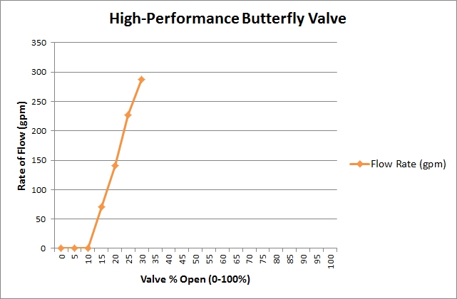
Rate-of-Flow Versus Valve Open % Measured at a Ground Storage Tank Fill Valve.
Note the large flow rate increase that occurs between 10% and 30% open.
(30-100% open could not be tested without pulling the upstream pressure down too low.)
Next Generation Valve Control Technology
In order to more precisely control valve flows and pressures, we recently researched the latest technologies in order to locate an improved control valve that would deliver a more linear rate-of-flow increase across the entire fully-closed to fully-open spectrum. If the rate-of-flow could be throttled more evenly across the majority of the actuator movement, then much more precise control of pressure and flow would be the result. As a result, we were led to the V-Port/Baffled Segmented Ball Valve. Based upon the unique shape of its V-notched segmented ball and baffle plates, it was postulated that the rate-of-flow through this quarter-turn valve would increase more evenly from 0 to 100% open.

V-Notched, Segmented Ball Valve with Anti-Cavitation/Noise-Reducing Baffles.

V-Port/Baffled Segmented Ball Valve – Principle of Operation Diagram.

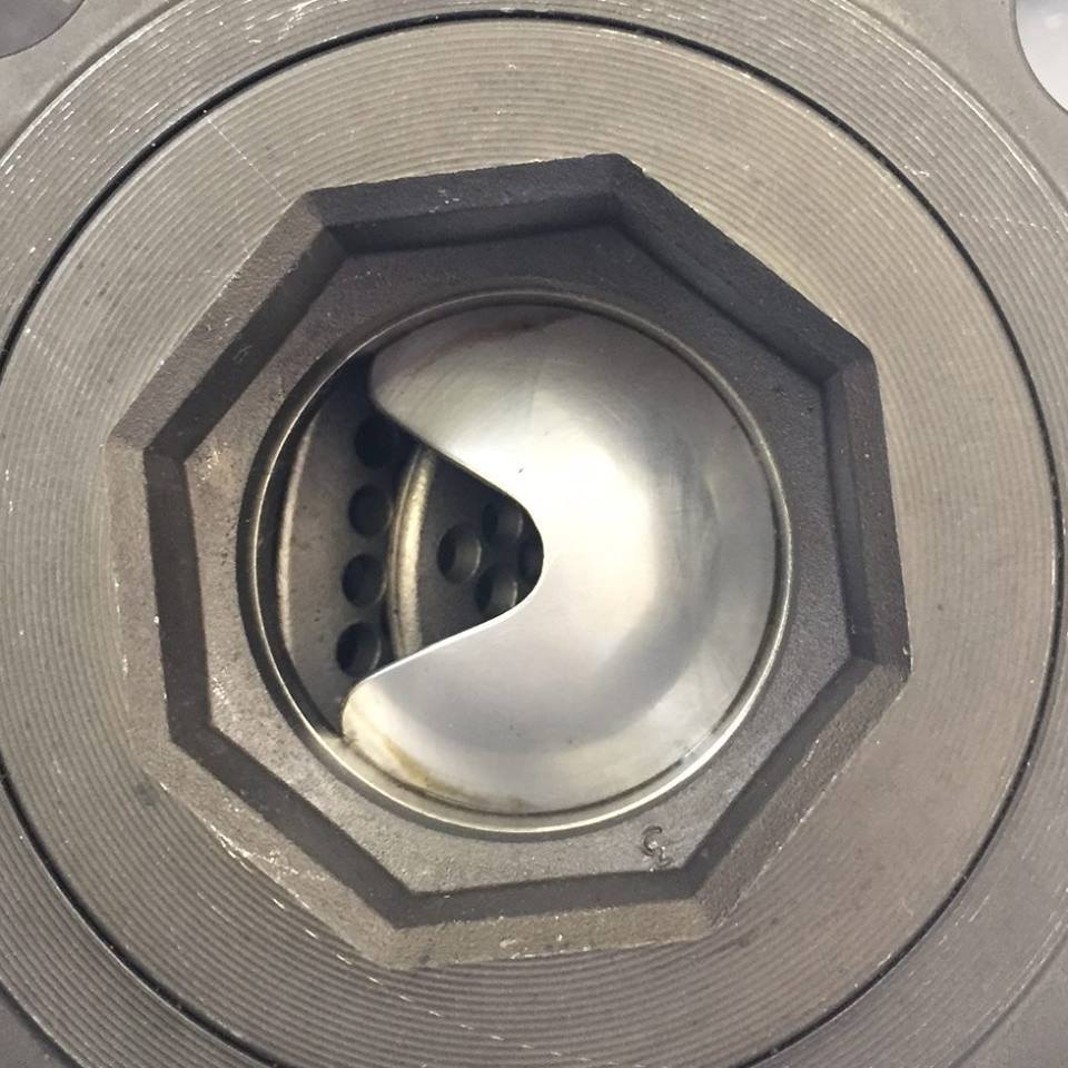
Internal View of a V-Port/Baffled Segmented Ball Valve – On the Bench Before Installation.
Photo Courtesy of Kurt Neuhaus of ERTC-SIUE
The following photos illustrate several cross-sectional views of the valve throughout the actuation spectrum:


Photos Courtesy of Kurt Neuhaus of ERTC-SIUE


Application Success Story
At Fosterburg Water District (Fosterburg, IL), each of their two pump houses had a diaphragm-type ground-storage fill valve that was approaching end-of-life; and Fosterburg had coincidentally been in search of a valve technology that could be tightly integrated into their controls. After a site visit to the valve distributor to see a V-Port/Baffled Segmented Ball Valve up-close, Fosterburg decided to proceed with an upgrade to the new valve.
District general manager and operator Mark Voumard provided pressure and flow datalogs to both the valve representative and the District’s consulting engineer (Heneghan & Associates, Jerseyville, IL), who each calculated the optimal valve diameter and baffle options based upon hydraulic computer simulations.
The photo below illustrates the original valve, flow meter, and piping within one of the District’s Pump Houses:

Wenzel Pump House at Fosterburg Water District. Note the influent line to the ground storage tank that features a turbo meter and a solenoid-actuated, diaphragm-type fill valve.
The photos below illustrate the removal of the old diaphragm valve and turbo meter… followed by the installation of the new valve and Siemens FM Mag 8000 electromagnetic flow meter:

Old Valve and Meter Section Removed from Service.

New Valve and Flow Meter Section Put Into Service.
Note the Shorter Lay-Lengths of the New Valve and Electromagnetic Flow Meter.

The Electrical Hookup to the Valve Was Relatively Straightforward: 120VAC Single-Phase Power, Grounding, 4-20mA Analog Positioning Signal from Telemetry Control System.
Validation Testing:
After the valve installations were completed, tests were performed to validate whether they were providing the desired linear flow-versus-actuation profile. During the tests, each valve actuator was re-positioned at 5% increments and flow measurements were performed. The performance, as illustrated by the following charts, was excellent:

Flow versus Actuation. Note that the flow variation was highly linear from 5% to 75% actuation. (75-100% open could not be tested without pulling the upstream pressure down too low.)

Flow versus Actuation. Note that the flow variation was highly linear from 10% to 80% actuation. (90-100% open could not be tested without pulling the upstream pressure down too low.)
Logic Programming and Telemetry Upgrades:
After the installation and validation testing, the telemetry controls were updated with sophisticated logic programming to provide Fosterburg with tighter monitoring and control of its valve actuation process. The following new setpoints were added:
- Back-Pressure Sustaining Pressure (PSI)
- Maximum Allowed Rate-of-Flow (GPM)
- Ground Tank Valve Open Level (Ft)
- Ground Tank Valve Close Level (Ft)
- Maximum Allowed Valve Speed (%/sec)
- Maximum Allowed Valve Position (%)
Feedback Control Test:
As an extreme test of the telemetry control system’s new feedback control mechanism, an upstream valve to the pump house was throttled to restrict flow. This restriction simulated an upstream low pressure condition, which could occur in situations where the bulk water supplier suffered from a main break. As the upstream valve was throttled to a near-close, the measured upstream pressure began to drop and dipped below the “Back-Pressure Sustaining Pressure” setpoint. The telemetry controls promptly modulated the V-Port/Baffled Segmented Ball Valve to a position that further limited the rate-of-flow so as to maintain the target upstream pressure.
Telemetry Historical Trends:
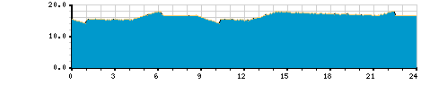
The following history charts illustrate the valve performance at the Wenzel Pump House on a typical day, as measured and logged by Fosterburg’s wireless telemetry system:
Ground Storage Tank Level – 24 Hour Chart.

Valve Position (%) – 24 Hour Chart.

Rate-of-Flow – 24 Hour Chart.

Upstream Pressure – 24 Hour Chart.

Totalized Gallons – 24 Hour Chart.
Lessons Learned:
- Unlike a butterfly valve, the V-Port/Baffled Segmented Ball Valve has a preferred flow-direction, and therefore the actuator orientation should be specified when ordering.
- The Baffle Plates not only increase the flow linearity, but they were also observed to provide lower sound emissions than an equivalent high-performance butterfly valve.
- In our logic programming, the valve position is modulated based upon a combination of inlet pressure, rate-of-flow, and maximum allowable open %. Experience has shown that it is best to select setpoints in a way that the valve position is primarily controlled by the maximum allowable open % — because this results in the fewest start/stops of the actuator — and minimizing the number of start/stops will lengthen the life of the actuator motor.
- We utilized a segmented ball valve, instead of a full-bore ball valve. The segmented ball provides the desired flow-control profile, has a lower cost, and requires less torque (smaller actuator).
Special Thanks:
Special thanks to General Manager Mark Voumard and the Board of Directors at Fosterburg Water District for the opportunity to perform this challenging project — a project which advanced the state-of-the-art in Rural Water telemetry & control.
Thanks also to Kurt Neuhaus, Paul Shetley, and the staff at ERTC-SIUE (Environmental Resource and Training Center – Southern Illinois University at Edwardsville) who generously provided photos used in this article.
Resources on the Web:
Before initiating a new flow control valve project, it is critical that water utility personnel take care to select the appropriate valve diameter size and baffling options. For assistance, please discuss with your consulting engineer, or utilize a valve sizing calculator:

Online Valve Sizing Calculator (by J Flow Controls)
Interested?
Would our state-of-the-art, V-Port/Baffled Segmented Ball Valve technology help solve a control challenge in your Water District? Give us a call. Our Telemetry/Control Systems are designed to leverage this exciting technology; and we’ll be glad to discuss this with you in further detail.
Telemetry, SCADA, & Controls Newsletter
Was this article helpful? Would you be interested in receiving updates such as these in our occasional email-delivered newsletter? If so, here’s our sign-up page:
Subscribe to Navionics Research’s “Telemetry, SCADA, & Controls Newsletter”