Jim Mimlitz, NRI
Since 2012, Navionics Research has been proud to serve the District as its Control Systems Integrator. The on-site monitored and controlled equipment includes level-sensing instrumentation, two 400 HP pumps and associated variable-frequency drives, power & voltage meters, and a rainfall analyzer. Through the control system user interface, District personnel are able to monitor the status and operational history; and they also receive cell phone text message and email alarms for key events, such as a pump turning ON/OFF, high water level detected, or a power failure.
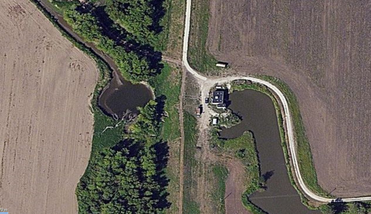
Pumping Station. Levee (Center), Ditch (Right), Canal to River (Left).
A key to the system’s efficient operation is accurate and reliable measurement of water levels in both the ditch and the river. The level of water in the ditch is important, as the pumps are directed to turn ON when the ditch reaches a high-level threshold and OFF when the ditch reaches a low-level threshold. The level of water in the river is also important, as certain pumps are limited to a restricted head pressure range. And both levels, when combined with pump speed, pump curve, and system curve information, can be used to estimate rate of flow and totalization. However that topic is worthy of a future article, and therefore will not be further addressed here.
There are various instrumentation methods available to monitor the water levels. However, this paper will focus on a Pneumatic Bubbler Transducer method. Our method utilizes a pneumatic pump, air sensing lines, transducers, and valve & control components.
The submerged transducer method, which was initially installed at the Levee District, but recently replaced during an upgrade, suffers from several disadvantages. First, the submerged transducers are generally staged at significant distances from the Control Building, and so they tend to be more susceptible to lightning damage and ground loops. Also, any electronic instrument that is submerged in water has the potential to suffer from water ingress eventually, even if the device is IP68-rated and designed for that purpose. Furthermore, the use of a submerged transducer requires a skilled installation contractor who understands the potential pitfalls and how to avoid them.
The Pneumatic Bubbler Transducer method does not require an IP68-rated pressure transducer, as the transducer is installed within the dry environment of the Control Building. Also, the pressure transducers are installed within the same cabinet (or near) the main controls, and therefore the risk of lightning damage and ground loops is abated. The following diagram illustrates the operation of a Pneumatic Bubbler Transducer level sensing system:

Level Sensing — Based Upon Polyethylene Tubing-Based Bubbler System
The following photos show the Pneumatic Instrumentation, which was packaged within a dedicated enclosure, and connected to the main control panel:

Pneumatic Pump, Transducers, Valves, and Controls.

Controls and Telemetry Package. Note the relative simplicity of the wiring due to a high-degree of networked, distributed instrumentation

Pressure Transducers: Keller ValueLine, 0-15 PSIG. Signal Output: 4-20mA
Installation Photos…

Installation of the Polyethylene Tubing into the Ditch-Side Stilling Well. Jim Mimlitz, Navionics Research (left), Hank Borrenpohl, Okawville Electric (right).

The End of the Polyethylene Tube Is Weighted So As Not To Float When Filled With Air.

Ditch-Side Stilling Well After Installation of Tubing.

Installation of the River-Side Tubing. Hank Borrenpohl, Okawville Electric.

River-Side Sensing Tube, Post-Installation. Note the Visible Flow from the Pump Discharge Pipe.

Telemetry Display Shows Realtime Performance Data.

Telemetry History Charts. Performance Is Shown A Few Days After Installation of the Pneumatic Bubbler Level Sensing Improvements.
It is important to note that this measurement technique could be applied not only to Levee District controls, but to potable water, as well. For example, for surface-water-based potable water plants, this system could be used to monitor the lake or river level at the raw water intake. For well-based potable water plants, this system could be used to monitor the water table level within the wells. In either case, when the measured level is too low, the controls would be programmed to automatically shut down the pump(s) in order to prevent pump cavitation. Another potential application of this system would be to monitor the liquid levels within chemical tanks at filtration/treatment plant facilities.
Notable improvements which were made after the initial installation include:
- The addition of an adjustable pressure regulator to limit the pressure emanating from the compressor pump.
- The addition of pressure snubbers for each transducer and gauge — thereby stabilizing the readings when the compressor is pumping.
- The use of stronger compression-fittings, rather than quick-disconnect fittings, for the submerged brass fittings (weights) at the polyethylene tubing terminations.
- The addition of an influent air filter for the compressor pump.
Would our Pneumatic Bubbler Transducer-based level sensing system help solve a control challenge in your Levee District or potable water treatment plant? Give us a call. Our Telemetry/Control Systems are designed to leverage this exciting technology; and we’ll be glad to discuss this with you in further detail.
Telemetry, SCADA, & Controls Newsletter
Was this article helpful? Would you be interested in receiving updates such as these in our occasional email-delivered newsletter? If so, here’s our sign-up page:
Subscribe to Navionics Research’s “Telemetry, SCADA, & Controls Newsletter”
With great interest I looked at this post. The self built Bubbler piqued my interest. I’m assuming that you are using the Keller units as the sensing element(s). I wondered about the 4-20ma outputs, A/D resolution of your DCP, dropping resistor (250 Ohms?) and excitation voltage, etc. I also wondered about the calibration method you used for this. I also wondered about the methods you use for purging the lines? We use neoprene tubing for Bubbler Line in our deployments. I wonder how the teflon tubing will hold up in the elements?
Your installation looks interesting. A lot of integration went into this. You didn’t get into the telemetry aspect but I’m sure that this will be in a future installment.
Hello Dave!
Thanks for your comments.
We are using the Keller ValueLine transducers as the sensing elements, and we are using them in 4-20mA output mode. Each transducer is excited with 24VDC power, and each mA signal is sensed across a 250 ohm precision resistor, which are built into the A/D converters in the telemetry panel (Advantech ADAM 4019+, 16-bit A/D Converter w/ Modbus/RTU).
I mis-spoke in the article about the tubing — We actually used polyethylene 1/4 inch outer diameter. It has held up well through a couple freezes, but attaching the 1/4 inch couplings (weight to hold the tube under water) using the quick-disconnect-type fittings was a mistake, as they did not hold in a submerged situation, so we went back and used compression fittings instead.
There were also a couple other later improvements…
First, it was immediately evident that pressure snubbers were needed at the transducers and gauges, as the diaphragm air pump caused the pressure to fluctuate wildly during purging.
Secondly, we added a small pressure regulator to the output of the diaphragm air pump to protect the transducers and gauges from over-pressurization — which could potentially occur if the tubing ever became clogged.
That’s the thing about integrations. We design with the best thoughts (in the design) but find that the long term data uncovers something that we have overlooked. Part of the learning curve I think. Most of my solutions happen in software (once the physical problems have been identified). Even after 22 years of hands on – I’m still learning the ropes. ;D
It’s gotten interesting in the last few years. The equipment has evolved to the point of where the game has changed. With IP based systems, integration and telemetry methods have changed. Interesting work. I’m sure you agree.
Thanks for the LinkedIn inquiry.
Pingback: Levee District Telemetry: Pump Flow Rate Estimation | Wireless Telemetry