Jim Mimlitz, NRI
Has your interest been piqued? Well, we’ve only scratched the surface. In fact, there are even more advantages to our new VFD & Energy Analytics Package.

Installation Complete:
Circuit Breaker / Load Reactor Panels (Partially Shown Left).
New PowerFlex 400 Variable Frequency Drives (Right).
In the 3rd and final installment of this article, we will discuss:
- VFD Fault Alarming and Remote Reset
- Elimination of Pump-Induced Water
- VFD Temperature Monitoring and Alarming
- VFD Health Monitoring and Alarming
- Pump Efficiency Monitoring
- VFD Network Communications
- VFD Terminal Block (Backup) Controls
- Faster-than-100% Pump Speed
- Utility Rebates
- Power Factor Correction
- 3-Phase Power Generation From Single-Phase Power
Any of the above topics would be worthy of an in-depth analysis, and perhaps a few more focused articles will be forthcoming, but for now a brief synopsis will be given.
VFD Fault Alarming and Remote Reset
VFD’s have additional internal protections that go above-and-beyond those in a typical across-the-line motor starter. For example, when a momentary overvoltage is detected, the VFD will shut down and report a fault code on its LCD display. The VFD will not allow a restart until the operator acknowledges the alarm by pressing the RESET button on the VFD keypad.
A common problem faced by VFD users is the occasional nuisance fault, which requires travel to the remote site to press the VFD RESET button. This can be particularly bothersome for water utilities who suffer from poor electric power quality. However, these problems can be alleviated — NRI’s new VFD & Energy Analytics Package provides the operator with instant alarm notifications via the SCADA system when a VFD fault is tripped. The operator is also notified of the nature of the fault (the actual fault code), and he is able to acknowledge and reset the fault remotely at his discretion. This acknowledgement/reset may even be performed remotely using a smart phone, such as an iPhone or Android.

VFD Faults May Be Remotely Viewed And Reset Using A SmartPhone.

Any VFD Faults That Occur are Available from the VFD via the Network.
Water Hammer Reduction
The featured Williamsville booster pump station was equipped with soft starters before the installation of the VFD upgrade. Their soft starters provided a 30-second ramp-up and ramp-down of the pumps, but Williamsville still saw significant water hammers right at start-up and shut-down. The VFD upgrade, however, was programmed to provide a 300-second ramp-up and ramp-down, which completely eliminated all pump-induced pressure spikes, as illustrated in the following before and after Telemetry history charts:
Pressure Charts Before VFDs…

Discharge Pressure (PSIG) — An Earlier History Chart when Booster Station was equipped with Soft Starts. Note the pressure spike at pump start-up at approx. 7:15am.

Suction Pressure (PSIG) — An Earlier History Chart when Booster Station was equipped with Soft Starts. Note the pressure spike at pump start-up at approx. 7:15am.
Pressure Charts After VFDs…
Discharge Pressure (PSIG) — A Later History Chart after the Booster Station was equipped with VFDs. Note the lack of pressure spikes at pump start-up at approx. 5:30pm.
Suction Pressure (PSIG) — A Later History Chart after the Booster Station was equipped with VFDs. Note the lack of pressure spikes at pump start-up at approx. 5:30pm.
VFD Temperature Monitoring and Alarming
Eventually, all cooling fans fail. As a moving part subject to wear — It’s simply a fact of life — And every VFD is equipped with active cooling fans for protection against current-generated heat buildup. The VFD Analytics Module, though, is capable of monitoring and alarming the VFD Heat Sink for extreme temperatures, allowing the owner to detect and repair a broken fan before the entire VFD fails due to overheating.
Also, VFD’s are occasionally installed outdoors — for example within a NEMA-3R outdoor package — and these units can be subject to both hot and cold extreme temperatures. To protect the drive electronics, the enclosure is typically outfitted with additional thermostat-controlled cooling fans and heaters. The fans, heaters, and thermostats, though, are also subject to failure. The VFD Analytics Module can detect and alarm any over-temperatures or under-temperatures — thereby allowing the owner to detect and repair the temperature controls before the entire VFD fails.
VFD Heat Sink Temperature May Be Viewed and Alarmed — Particularly Useful for the Detection of Enclosure Fan or Heater Failures.
VFD Health Monitoring and Alarming
If a VFD suffers a non-resettable failure, one of the first on-site troubleshooting steps is to verify that the drive is holding the correct DC bus voltage: 1.41 x Station Voltage. The PowerFlex drive even has multimeter hookup terminals dedicated to helping the technician perform this function. The VFD Analytics has a built-in function to extract the DC Bus Voltage, display the value on the Telemetry screen, and generate alarms when the Bus Voltage falls outside of specifications.
VFD DC Bus Voltage. A Healthy VFD Has A Bus Voltage of Approximately 1.41 x Station Voltage. In this Instance of a 230VAC Station, the DC Bus Voltage Should Be Approximately 325VDC.
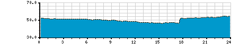
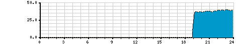
The Analytics software can also extract and present important electric power output data —namely speed, voltage, current, kilowatts , and kilowatt-hour information:
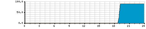
VFD Output Speed (%) – 24 Hour History Chart
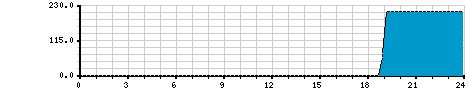
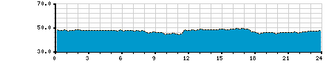
Motor Voltage (VAC) – 24 Hour History Chart
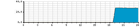
Motor Current (Amps) – 24 Hour History Chart

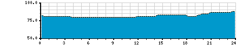
Motor Power Consumption (KW) – 24 Hour History Chart
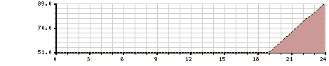
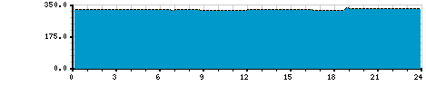
Motor Accumulated Energy Consumption (KWH) – 24 Hour History Chart
Pump Efficiency Monitoring
The pump efficiency is defined as the ratio of Pump Work to Pump Electric Power Consumption. Using the new tools at our disposal, this performance measure may be calculated and tracked in realtime:
- Pump Power Consumption (KW) — From VFD Analytics
- Flow Rate (GPM) — From EtherMeter & Flow Meter
- Pump Head Differential (PSI) — from Pressure Transducers
Efficiency = PumpWork(kw) / VfdPowerOutput(kw)
Efficiency = [FlowRate(gpm)x[Discharge(psi)-Suction(psi)]/2302] / VfdPower(kw)
Pump Efficiency May Be Derived and Monitored Using KW (from VFD), Flow Rate (from EtherMeter), Discharge & Suction Pressures (from Transducers).
VFD Network Communications
In order to implement advanced VFD control and monitoring, it was imperative that our preferred VFD offer integral networking capability as a standard, non-optional feature. Additionally, it was imperative that the VFD offer that networking in the form of a non-proprietary communication protocol — such as Modbus, EtherNet/IP, DF1, and/or BACnet.
A non-proprietary protocol — such as Modbus — is one that adheres to an international communication standard and ensures that equipment from multiple vendors can co-exist on the same network within a pump station. When a proprietary VFD networking protocol is introduced into a pump station control network, additional expense and risk is assumed by the customer, as he becomes locked-in to the whims of a single VFD vendor.
The PowerFlex 400 VFD offers non-proprietary, Modbus network communications standard on all size and voltage combinations.
Modbus has become a de facto standard of industrial
communication protocols. Gathering momentum and support since 1979 when it was first introduced by Modicon (now a division of Schneider Electric), it is the most common means of connecting industrial electronic devices. It is openly published, royalty-free, and forms a relatively easy-to-deploy industrial network.
VFD Terminal Block (Backup) Controls
Good engineering practice demands that we provide an alternative control path in addition to the Modbus network control. For example, should the Modbus network fail, then we would still like to be able to run and monitor the pumps automatically using the Telemetry Controls. To accomplish this, we recommend an alternative backup control method — implemented via the VFD’s terminal block. In case of Modbus network failure, the Operator may toggle the VFD Control to “Discrete Control”, which will cause the Telemetry to run the pump(s) when required at a preset speed with soft-starts and soft-stops.

As a Backup to Digital Network Control, Discrete Terminal Block Control of the VFD Should Be Implemented.
Faster-than-100% Pump Speed
If a pump motor has available, unused horsepower at 100% speed (60 Hz), it is possible to run the pump at speeds greater than 100%. For example, during a period of emergency high water demand, or perhaps as a method of increasing the flow capacity of a pump station without changing out the pump. When using network-based control, greater-than-100% speed is easily achieved and generally does not require additional on-site modifications.
Utility Rebates

Due to the energy-saving nature of VFD’s, along with their associated reduced motor starting currents, many Power Utilities are offering monetary incentives to Water Utilities to upgrade across-the-line starters in pump stations and water plants to VFD’s. Before embarking on a VFD project, it is certainly worth investigating whether your Power Utility offers any sort of rebate or incentive plan. Some useful links are provided below.
ILLINOIS:
When available, the rebates in Illinois are typically around $100 per HP per pump. For example, for a 2 pump station where each pump is 75HP, the rebate might be $15,000.00.
MISSOURI:
When available, the rebates in Missouri are typically around $50 per HP per pump. For example, for a 2 pump station where each pump is 75HP, the rebate might be $7,5000.00.
Power Factor Correction
A 3-Phase Motor with an across-the-line starter presents an inductive load to the Power grid — a less-than-unity power factor — which in basic terms means that the current-voltage product exceeds the stations wattage, thereby posing challenges for the Power Utility’s generation and distribution grid. A VFD’s power factor, on the other hand, is very close to ideal (1.0) — and therefore corrects for the motor’s inductive load.
Typical Motor Power Factors (from Engineering Toolbox)
| Power (HP) | Speed (RPM) | Power Factor | ||
| ½ Load | ¾ Load | Full Load | ||
| 0-5 | 1800 | 0.72 | 0.82 | 0.84 |
| 5-20 | 1800 | 0.74 | 0.84 | 0.86 |
| 20-100 | 1800 | 0.79 | 0.86 | 0.89 |
| 100-300 | 1800 | 0.81 | 0.88 | 0.91 |

VFD’s Offer Power Factor Correction, As Illustrated on the Power Meter at the Williamsville Booster Station During a VFD-Driven Pump Run Cycle: Power Factor=0.984
3-Phase Generation from Single-Phase Power
Certain remote pump station locations are not served by 3-phase power, or the expense to bring 3-phase power to the remote stations can be excessive. In the past, this problem was solved by introducing add-a-phase machinery into the station to generate 3-phases from single-phase power. With a VFD, though, the add-a-phase machinery is no longer needed, as a drive is capable of generating 3-phases from single-phase power. Keep in mind that the VFD must be over-sized when used in such an application.

VFD’s Can Produce 3-Phase Power from Single-Phase, A Task Generally Accomplished in the Past Using the Add-a-Phase Rotating Machinery.
Documentation
When a VFD is provided and installed, it is imperative that full documentation be provided, so that future service or replacements can be handled easily:
- Make & Model w/ Full Part Number
- Personality Settings (Motor Nameplate Values, Terminal Block Settings, Comm Settings, etc.)
- User Manual
- Fault Code Table
- Wiring Diagrams
For our standard VFD, the PowerFlex 400, we have developed and maintain special documentation that focuses on the specifics of pump station installation, setup for communications with VFD & Energy Analytics software, terminal block wiring, and a fault code table:
- NRI Application Note: Wiring Diagrams, Personality Settings, Fault Code Table
- PowerFlex 400 User Manual
Conclusions
Thank you very much for tuning in to this 3-part series! We covered a lot of material, and I hope you found useful information. Is it possible that our new VFD & Energy Analytics Module may benefit your water or wastewater utility? Give us a call, and we’ll be glad to discuss this with you in further detail.
Prologue
As a follow-up to our 3-part series, please visit the Series Prologue (LINK Here) to learn more about our upgrade procedures, policies, and future directions.
Pingback: Introducing VFD & Energy Analytics for Telemetry, SCADA, and Control Systems — Prologue | Wireless Telemetry
Pingback: [BLOCKED BY STBV] Introducing VFD & Energy Analytics for Telemetry, SCADA, and Control Systems — Part 2 of 3 | Wireless Telemetry